Fixed Bias - zener diodes and resistor fallback
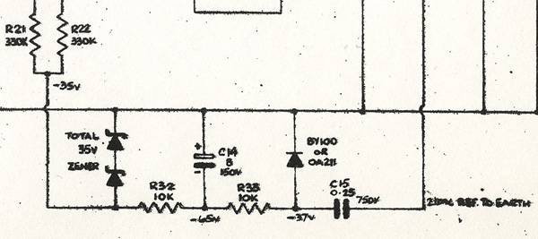
Detail from a late schematic. Click for a larger version. At right, the legend is "210V REF. TO EARTH". The sheet as a whole is available on this page.
The fixed bias network in the "100W Amplifier" and the AC100 Mk2 is simple and ingenious. Voltage comes in from one side of the rectifier bridge - 210v as marked on the sheet. Capacitor (C15) smooths the ripple current and and drops the voltage to around 100v. The diode that follows turns the voltage negative, shunting any residual positive voltage to ground. Then come two dropping resistors (R33 and R33) and a smoothing capacitor (C14), followed by the zener diodes, one of 20v the other 15v, which together clamp the bias at -35v.
The zeners were produced by the International Rectifier Corporation, its UK subsiduary having beem established in Oxted, Surrey, in 1960. Their part numbers are MZ20 and MZ15. Power handling is 3/4W. The package format: "T5" - gold-coloured, metal-cased "top hat". Gold-coloured diodes were generally a sign of higher than normal quality (as used by the military). See the foot of this page for further details.
The really clever thing about the circuit is that if either of the zeners fails, the negative voltage from resistor R32 is enough to keep the bias of the valves at around -40v. The resistor network was evidently carefully designed.
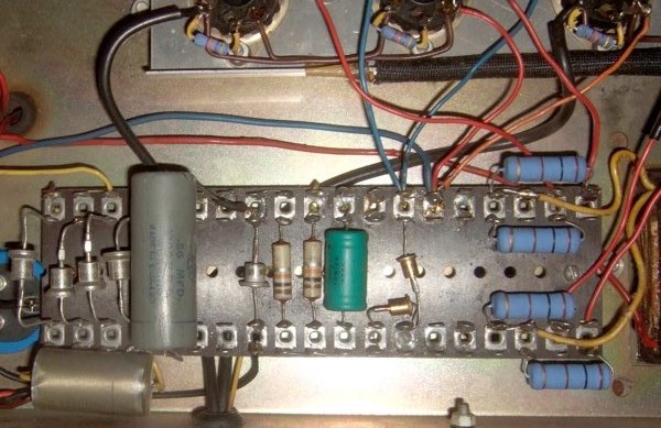
Above, the untouched bias network of serial number 531.
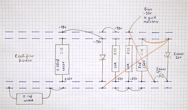
A rough and ready diagram of the network. Again, click for a larger version. The wires in brown are hidden underneath the tagboard. The voltage from one half of the rectifier bridge is taken up at left (fourth tag from the left, lower row). The network as a whole is earthed at the inverter diode (sixth tag from the right, lower row).
Despite the cleverness of the circuit, there are two main drawbacks:
(1) The bias is fixed and incredibly low (by modern standards), a drawback in the US, where wall voltages were, and are, generally higher than 110v, driving up the voltage on the plates and screens of the output valves, thereby requiring a bias greater than -35v (which is invariable due to the clamping of the zeners). Fixed bias itself is not a particular drawback though - a zener of a higher value can easily be substituted for the smaller one (15v). The only requirement is for a well-matched quad of EL34s.
(2)The routing of the -35v through the 330K grid resistors is not a particularly good idea, as they tend to act as voltage droppers. One can have -35v issuing from the zeners, but only -33v on the valves themselves.


